|
 Routing:
[Gen][CCNA][CCNP Route][CCNP Remote][CCDA][MPLS][EEM][Add][Juniper][ACL][Host]
Routing:
[Gen][CCNA][CCNP Route][CCNP Remote][CCDA][MPLS][EEM][Add][Juniper][ACL][Host]
Switching: [CCNP Switch] [Switch Add] [Intro] [VLANs] [MLS] [STP] [QoS] [Availability] Security: [CCNP Security] [CCNA Security] [CCNP ISCW][PIX] [Adv PIX/ASA] [Net Sec1] [Net Sec2] Wireless: [Wireless] [Wireless Chall] [CCNA Wireless] [Wireless Theory] Voice: [Voice/QoS] [CCNA Voice] [CCVP Gateway] [CCVP Voice] Topics: [Dot1q][Dot1x][BGP][BRI][DHCP][IGRP][IGMP][OSPF][PPP][QoS][RADIUS][RIP][Subnet][SNMP][VLAN] VLANsA VLAN (Virtual LAN) is a network which constrains the broadcast domain. Within a VLAN all the hosts can directly communicate with each other. CCNA Challenges
CCNP Switch
Wireless
PIX/ASA
CCNP ONT
CCVP (Voice)
CCNA Wireless
CCNA SecurityCCNA Voice
OutlineA major problem in the past has been security and contention on Ethernet network. Switching overcomes both these problems as it can create vLANs (Virtual LANs) which allow nodes to be isolated from each other, even though they connect to the same device. Switches avoid the problem of contention on a network, as they take frames from one interface, and forward it to another. This can take place at either Layer 2 (Data Link layer) or Layer 3 (Network Layer). Routers implement Layer 3 switching to route data packets and switches (Layer 2 switches) use Layer 2 switching to forward frames. In Layer 3 switching the router examines the network address, and decides on whether it should forward it to another port, whereas with Layer 2 the switch examines the MAC address of the data frame (it thus ignores any network layer information). A Layer 2 switch must build and maintain a switching table that keeps track of the MAC addresses that belong to each port or interface. As with the ARP protocol, the Layer 2 switch sends out a broadcast on all of its ports if it does not know where to send a data frame. When the addressed node detects its address, it sends back an ARP reply, and the switch adds the new address to its switching table. The MAC address itself is a 48-bit address, made up of the manufacturing (MFG) code and the unique identifier. Organizations have no control over MAC addresses, and they have a flat addressing structure, whereas Layer 3 address are typically organized in a hierarchical way, typically using IP, IPX or Apple-Talk addresses. vLANs are a new technology, which uses software to define a broadcast domain, rather than any physical connections. In a vLAN a message transmitted by one node is only received by other nodes with a certain criteria to be in the domain. It is made by logically grouping two or more nodes and a vLAN-initialized switching device, such as intelligent switches (which use the MAC address to forward data frames) or routers (which use the network address to route data packets). The important concept with vLANs is that the domain is defined by software, and not by physical connections. There are two methods that can define the logical grouping of nodes within a vLAN:
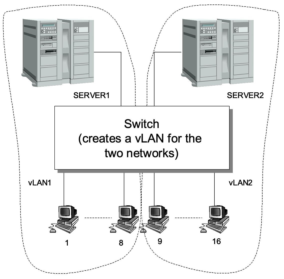
It is thus difficult to create truly compatible vLANs until standards for implicit and explicit tags are standardized. One example of creating a vLAN is to map ports of a switch to create two or more virtual LANs. For example, a switch could connect to two servers and 16 clients. The switch could be configured so that eight of the clients connected to one server through a vLAN, and the other eight onto the other server. This setup is configured in software, and not by the physical connection of the network. Figure 1 shows a possible implementation where nodes 1 to 8 create a vLAN through the switch with SERVER1, and nodes 9 to 16 create a vLAN with SERVER2. The switch would map ports to create the vLANs, where the two networks are now independent broadcast domains (network segments), and will only receive the broadcasts from each of their virtual LANs. Normally a switch would connect any one of its ports to another port, and allow simultaneous connection. In this case, the switch allows for multiple connections onto a segment. Now, with the vLAN, data frames transmitted on one network segment will stay within that segment and are not transmitted to the other vLAN.
Figure 1 Creating a vLAN by mapping ports of a switchThe main advantages of using vLAN are:
There are also a number of key issues which need to be considered when installing a vLAN:
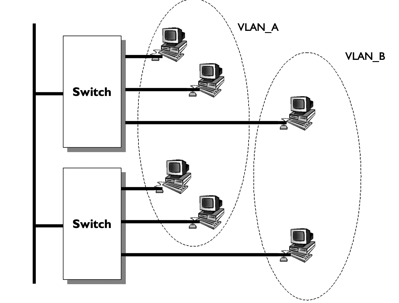
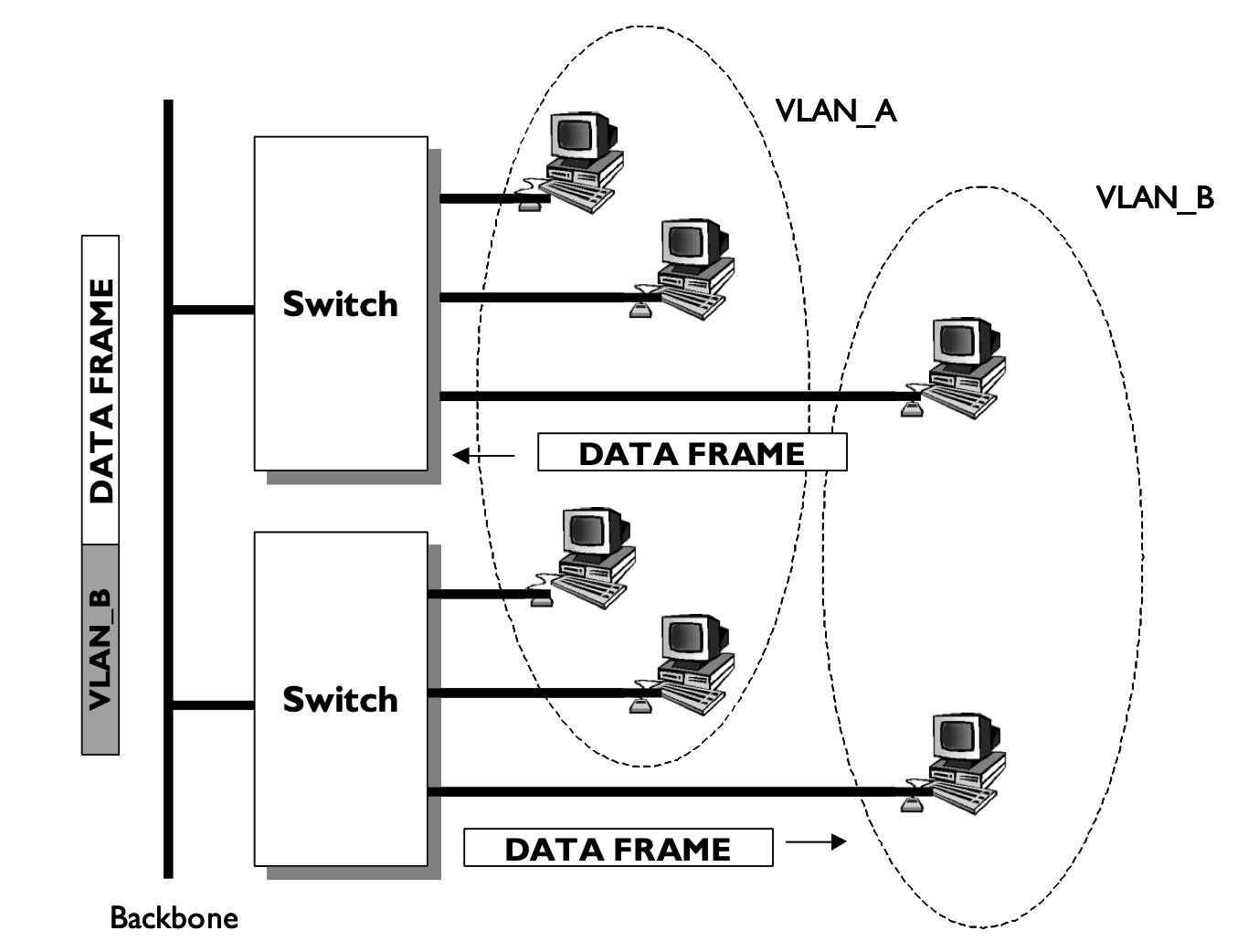
A vLAN can be created by connecting workgroups by a common backbone, where broadcast frames are switched only between ports within the same vLAN. This requires port-mapping to establish the broadcast domain, which is based on a port ID, MAC ad-dress, protocol or application. Each frame is tagged with a VLAN ID. Figure 2 illustrates that switches are one of the core components of a VLAN. Each switch is intelligent enough to decide whether to forward data frame, based on VLAN metrics (such as port ID, MAC address or network address), and to communicate this information to other switches and routers within the network. The switching is based on frame filtering or frame identification. Most early vLANs were based on frame filters, but the IEEE 802.1q vLAN standard is based on frame tagging, as this allows for scaleable networks. With frame tagging, each frame has a uniquely assigned user-defined ID. A unique identifier in the header of each frame is forwarded throughout the network backbone (vertical cabling), as illustrated in Figure 3. Each switch then reads the identifier, and if the frame is part of a network which it controls, the switch removes the identifier before the frame is transmitted to the target node (horizontal cabling). As the switching occurs at the data link layer, there is not a great processing time overhead.
Figure 2: vLANs using a backbone and switches vLANs rely on broadcasts to the virtual network, but they are constrained within the virtual network, and thus are not transmitted to other virtual networks. This should reduce the amount of overall network broadcasts (especially from broadcast storms). The broadcast domain can be reduced by limiting the number of switched ports which connect to a specific vLAN. The smaller the grouping, the lower the broadcast effect. vLANs increase security of data as transmitted data is confined to the vLAN in which it is transmitted. These provide natural firewalls, in which external users cannot gain access to the data within a vLAN. This security occurs, as switch ports can be grouped based on the application type and access privileges. Restricted applications and resources can be placed in a secured VLAN group. The two types of vLANs are:
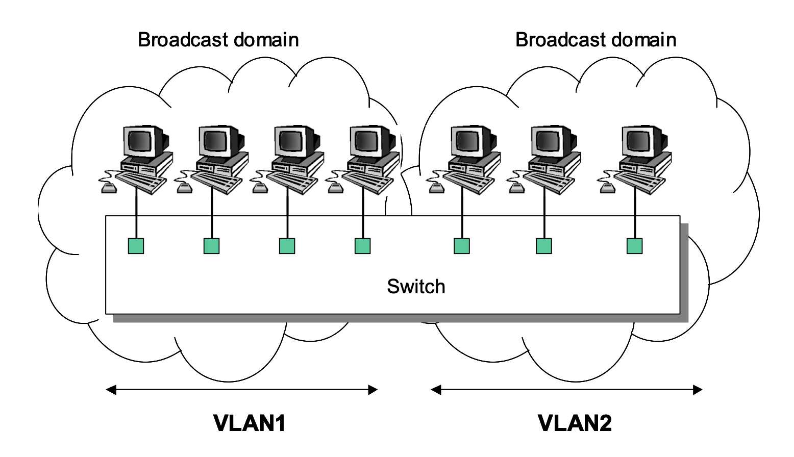
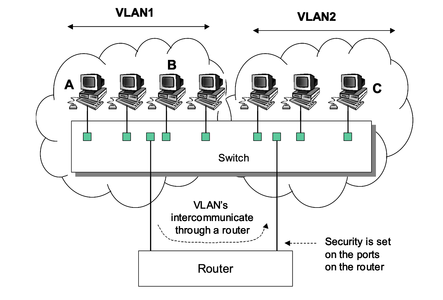
The broadcast domain in a vLAN is defined by each vLAN, as illustrated in Figure 4. A node broadcasting into the vLAN will only be transmitted to nodes within its vLAN. Nodes not connected to the same vLAN, even although they connect to the same switch as the broadcasting node, will not receive the broadcast. The only way for nodes to intercommunicate across differing vLANs is to be routed through a router (as illustrated in Figure 5).
Figure 3: vLANs using frame tagging
Figure 4: Broadcast domains for vLANs
Figure 5: Broadcast domains for vLANs Note that a broadcast domain extends the full length of the vLAN, and not onto other vLANs. A router does not forward broadcasts, thus the vLAN is isolated from other networks. The router provides intercommunicate between vLANs, and security is enhanced by implement security restrictions on the ports of the router. As previously mentioned the broadcast domain is important, as nodes use it to determine the MAC addresses of nodes within their vLAN. In Figure 5, a node on VLAN1 could only communicate with a node on VLAN2 if would use the network address of the node on VLAN2. For example if Node A communicates with Node B, it would broadcast an ARP request into its vLAN for the MAC address of Node B, which would return it back to the vLAN. Node A can then communicate with Node B, as it uses the MAC address of Node B, and its network layer address. If Node A wishes to communicate with Node C, it will send out an ARP request to the port on the router to which it connects to (its gateway). This port will respond back with its MAC address. Node A will then send out a data frame with the MAC address of the gateway, and the destination address of Node C. The router will then forward it onto the port which has Node C connected to it, and changes the destination MAC address to the MAC address of Node C (if it already knows it, else it would initially send out an ARP request for it). The router will generally test the incoming data frame for security purposes, and will only forward it if Node A is allowed to communicate with Node C (allowing for certain conditions). ConfiguringOne of the great advantages of switches is that it is possible to create a VLAN, which allows the actual topology of the network to be defined by software rather than actual physical connections. In the following the VLAN is given a name, and then ports are assigned to it. 1. Go to the privileged executive mode (that is, with the # prompt). 2. Use the show vlan command to view the currently assigned VLANs. What are the names of the currently assigned VLANs? 3. Use the vlan database command to go into the vlan configuration mode. How does the prompt change? 4. Use the ? command to view the commands in this mode. 5. Use the show command to view the currently assigned VLANS. What VLANs are currently present? 6. Use the vlan 2 name fred to change the name of VLAN number 2 to fred. What message is displayed? 7. Use the show command to view the currently assigned VLANS. Has the VLAN been added? 8. Exit from vlan and configuration modes, and run show vlan again. How have the names of the VLANs changed? Programming interfaces and assigning to VLANs: 1. Configure the interface by typing interface. How does the prompt change? 2. Determine the commands that can be used in the interface menu with ?. List a few of these command. What commands are available in Interface Configuration mode? 3. Program the first Ethernet port on the switch (which is 0/1, where the first digit identifies the Ethernet port and the second digit identifies the port number). Do this by entering the Ethernet 0/1 command. 4. Define the this port is assigned to VLAN 2 with the switchport access vlan 2 command. 5. Program the second Ethernet port on the switch (which is 0/2). Do this by enter-ing the Ethernet 0/2 command. 6. Define the this port is assigned to VLAN 2 with the switchport access vlan 2 command. 7. Go back to the Privileged Exec mode, and use the show vlan command to show the assigned VLANs against ports. A sample configuration is: > en # config t (config)# int vlan 2 (config-if)# ip address 148.183.229.5 255.255.248.0 (config-if)# exit (config)# int fa0/2 (config-if)# switchport access vlan 2 (config-if)# int fa0/5 (config-if)# switchport access vlan 2 (config-if)# exit (config)# ip domain-name perthshire.cc (config)# ip default-gateway 148.183.229.6 |